 | |||
 |
 |
 | |
 |
 | ||
 |
 | ||
 |  | ||
 |  | ||
| |||
|
|
|
| |
|
|
| ||
|
| ||
| | ||
| | ||
| Written by Paul D. Race for Family Garden Trains(tm)
and New Boston and Donnels Creek: |
 |
|
|
Framing the NEW New Boston and Donnels Creek RR, Part. 2If you've been following along with our planning, groundbreaking, and framing articles, you know that we moved in November, 2016 and have been planning and working on the new iteration of our railroad since March, 2017. The new version will be entirely raised, some of it quite high for vertical interest. All of it will be set on lumber, not on dirt, to avoid the problems of constant weeding and burrowing animals we experienced with our first railroad.This is, obviously a followup to our "Framing the NEW New Boston and Donnels Creek RR, Part. 1" article, in which I set the vertical posts and ran enough lateral pieces to connect them and keep the structure stable. I also started adding the frame pieces for what will become the "middle layer" of my three-tier raised railroad. One ongoing issue is the amount of lumber this is taking. The cost of materials is certainly going to be more than I spent on materials the first time around. But it's still likely to be cheaper than trying to achieve the same effect with posts, retaining walls, and several loads of dirt. And it should require far less maintenance in the long run. After I finished the assembly bits in the last article, I added a few more pieces of lumber, to use up my odds and ends before they warped. Adding Electrical Service To the Railroad Structure This is one of those "Don't Try This at Home" bits. I went ahead and hooked the wires coming out of the ground (left over from a previous owner's swimming pool) into a junction box and from there into two separate GFI outlets. Like everything else, I poured over all my different options before I selected one that would leave the GFI outlets in easy reach but allow for eventually running additional outlets to other parts of the railroad. This is one of those "Don't Try This at Home" bits. I went ahead and hooked the wires coming out of the ground (left over from a previous owner's swimming pool) into a junction box and from there into two separate GFI outlets. Like everything else, I poured over all my different options before I selected one that would leave the GFI outlets in easy reach but allow for eventually running additional outlets to other parts of the railroad.
By the way, there were two lines controlled by two separate circuit breakers on the panel in the garage. I was glad for this, because it meant I could dedicate, say, one circuit to trains and one circuit to lighting and other accessories. I realized before I started that work that one of the lines (the one with the big heavy conduit and the 12-gauge wire) was actually wired to deliver 220volts, not 110. So WITH THE POWER OFF, I changed out the circuit breaker and changed the service over to 15amp, 110 volts. I will NOT go into details about how I did this, since wiring codes vary from state to state, and there have already been enough accidents (and fatalities and structure fires) because someone saw an electrical wiring shortcut on YouTube or some such. If you're not experienced with house wiring and you don't have the codes virtually memorized, consider hiring an electrician before you do anything as complicated as running underground wiring to a backyard structure of any kind. If you do choose to do this yourself, follow all recommended safety regulations, including working only when the master circuit breaker is off, using UF cable (12 gauge is recommended), burying it at the right depth, using conduit where it is exposed to potential damage from weedwackers, etc., and making certain the circuit and all outdoor wiring is "ground-fault-interupt" protected. I'll also point out to people who know this stuff, that the gray wires you can see will eventually be stapled to the support board and have a deck installed over them, which is considered an acceptible practice in some - but not all - jurisdictions. The outlets you see will eventually be part of a structure with a roof - a mini-train shed attached to the railroad itself. For now I cover them with plastic when not in use. More DecisionsWith only half the framing installed on the "middle" section, I could still move in and out of the structure fairly easily. For a time I had considered finishing that section before starting on the upper railroad. Since the finished middle section will be a sort of deck that should easily support my weight, there's no reason I couldn't just clamber around on the thing. But I realized that it would be easier to attach the joists, etc for the upper railroad while I could still stand on the ground.But where, vertically to align it? I wanted 11"-12" of clearance between layers, and had the idea that right of way on the middle layer would go under the edge of the top layer in at least one place. As it turned out, I had not paid close enough attention to exactly where the middle layer went - it was a couple inches higher than I had planned. And that meant that there wasn't enough room to build the top layer the same way and still have as much vertical clearance on the top level as I wanted. Now, two "fixes" were possible:
So I decided on a "belt-and-suspenders" approach - do both. Because parts of the middle layer are still not finished, I still have the flexibility to widen it just a little if necessary (say by adding an extra 2"x6" on the outside of the frame where there is a "tight spot.") But I needed to frame out the top layer before I was entirely sure where it would overlap the planned ROW on the middle layer. Redesigning the Top Layer My earlier designs for the top layer incorporated a lot of redundancy and extra rigor, the sort of thing you'd need in a freestanding raised garden railroad that people might be bumping into and visiting children might even climb. There was a joist layer (shown in dark brown) and a separate layer of supports running the opposite way (shown in amber). This was the way you would build a backyard deck, more or less, and it would stand up to just about anything, including people leaning or even climbing on it. My earlier designs for the top layer incorporated a lot of redundancy and extra rigor, the sort of thing you'd need in a freestanding raised garden railroad that people might be bumping into and visiting children might even climb. There was a joist layer (shown in dark brown) and a separate layer of supports running the opposite way (shown in amber). This was the way you would build a backyard deck, more or less, and it would stand up to just about anything, including people leaning or even climbing on it.
As I tried to figure out how to sandwich this construction between the middle layer and the boards running around the top of my tall posts, I realized that I just couldn't afford the room that the "extra robust" structure would take up vertically. How could I reduce that without substantially reducing the sturdiness of the thing? No I wouldn't be standing on it, but you never know when someone might, say, lose their balance and find themselves putting more weight on it than they meant to. By the way, since I haven't mentioned this recently, the grid in these drawings shows 2' squares. So the posts are 6' apart one way and 3' apart the other way. Reviewing my earlier designs, I realized that the three joists were close enough together to put decking across without a separate support layer. For a level that few people would even reach, and hopefully nobody will be climbing on, I thought I could afford to lose some of the redundancy in my earlier designs.
The "weak point" in this plan would technically be that long, relatively unsupported middle part. But, again, nobody was going to be walking on it, and I had several options for fixing that if it became a problem. (If I was designing a free-standing railroad this way, I'd just add two more posts and a cross-piece in the middle, by the way.)
By the way, the cross-pieces are notched just in case, after all this planning, they are still too close to the ROW on the middle layer. Getting Started on the New PlanBy the way, you may get the impression that I suffer from "paralysis by analysis" - endlessly rethinking everything. I certainly did come up with a number of different plans before I had a chance to start digging holes. But once I start building things, a lot of ideas come about because I tried something that doesn't quite work out. Or once things start to come together enough to really visualize them, I realize there's a better approach.In this case, I actually tried an in-between solution that is not shown, fastening a few boards in place to test it, before I settled on this approach. Once I was sure where I wanted the next layer to go, I screwed two of the long boards (what would have been joists in my earlier design) to the posts. I screwed those directly to the posts, triple-checking levels as I did so. The rather unimpressive but critical result is shown at the right. The long boards I'm discussing are shown in yellow.
Yes I realize that in most sets of instructions, those cross-pieces would have gone on first. They probably will if I ever use this sort of plan again. But I measured and placed the first boards very carefully while I had some other pieces installed that have since been removed, so I knew they were "right. The next step was to connect the two long boards with short pieces that went over the ends. Then I put the third long board in the middle and fastened it in place, screwing it into the "caps" and toenailing it into the crosspieces. So the "plan" for the core frame of the top layer as I initially installed it shown at the right. The photo below shows that layer as it was first installed. The two boards with the notches are the crosspieces shown in reddish-brown in the drawings. The rectangular box sitting on top of them is shown in amber in the drawings. Once the middle long board was screwed into the end caps and tonailed into the crosspieces, it was very stable.
Yes, you may have picked up on the "first installed" wording in the paragraph above. The box part has stayed, will stay, right where it is. So will the cross-piece on the end closest to the camera. But once I had that part in place, I realized there was one more improvement I could add without undoing anything I had done so far. One More TweakAt this point, I could begin to see where the other pieces of that layer should go. And I realized that one more tweak would be helpful. The way our land slopes, I didn't think you'd see the waterfall from our back porch, so I hadn't taken that into account. But once I got this far along, I realized that you would be able to see it if it was turned the right way. And in almost all of my plans, including my most recent overall plans, it was facing the wrong way.
The extra cross-pieces will be installed to give a little more leverage/support to the short pieces on the right side of the table, where we have the cutout for the waterfall and bridge. BTW, I haven't bought any of the pond hardware yet, since I didn't know if my design would change so radically that I would be having to change that, too. In fact, I'm not deliriously happy with the pumps and filters I've seen so far - most of the ones with the features I want seem way overpriced, and frankly, overrated for what they really deliver. For example, a pump might say "1200 gallons per hour" but if you look closer, that's only if it's not having to pump water uphill at all. If you are pumping water uphill, say six feet, that drops to a trickle. For this iteration, I'll probably order a pump that will get me through the next couple phases of construction and worry about getting a bigger, more reliable pump if and when I install an actual pond.
I don't show the track in the picture to the right because I know I've aready allowed enough room for it, and it's a pain to redraw those curves precisely. :-) The main consideration is that the track must cross the "notch" at a straight line if possible. That seriously simplifies bridge-building. Of course, once this level is done, I can go back and finish up the middle layer. More lumber, of course. ConclusionAs you can see, doing this project a bit at a time allowed me to think and rethink. If I'd broken ground as soon as I had my original plan back in March, the result would have been nowhere near as nice as I expect it to be now. Since I'm designing what - for me at least - is a new kind of garden railroad, I can't help feeling that all the extra thought that has gone into this, both in design and in execution will pay off "big-time" once the plants and buildings are installed, and the trains and waterfalls are running.In the meantime, if I've helped you get any ideas at all for your next garden railroad construction, I will consider the time it took to document all of this time well spent. Best of luck, all, Enjoy your hobbies, and especially enjoy any time you can spend with your family in the coming season. Paul
Click on the photo to see our status as of September 17, 2017
Click on the photo to see our status as of August 10, 2017
Click on the photo to see our status as of the end of July, 2017
Click on the photo to see what we were considering as of late May, 2017
Click on the photo to see what we were considering as of late April, 2017
Click on the photo to see what we were considering in early April, 2017
Click on the photo to see what we were considering in March, 2017
|


|

Note: Family Garden Trains?, Garden Train Store?, Big Christmas Trains?, BIG Indoor Trains?, and BIG Train Store? are trademarks of
Breakthrough Communications (www.btcomm.com). All information, data, text, and illustrations on this web site are
Copyright (c) 1999, 2000, 2001, 2002, 2003, 2004, 2005, 2006, 2007, 2008, 2009, 2010, 2011, 2012, 2013, 2014, 2015, 2016, 2017 by
Paul D. Race. Reuse or republication without prior written permission is specifically
forbidden.
Family Garden Trains is a participant in the Amazon Services LLC Associates Program,
an affiliate advertising program designed to provide a means for sites to earn advertising
fees by advertising and linking to amazon.com.
For more information, please contact us
 |  |
| Visit related pages and affiliated sites: | |||||
| - Trains and Hobbies - | |||||
|  |
|
 |
|  |
 |

|

|  |
|

|
| - Christmas Memories and Collectibles - | |||||
 |

|
 |

|

|
|
| - Family Activities and Crafts - | |||||
 |

|

|

|

|

|
| - Music - | |||||

|
 |
 |

|

|

|

|

|

|

|

|

|

|

|

|

|

|

|


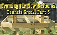 Proceed to "Framing the NEW New Boston and Donnels Creek RR, Part 3"
 Return to "Framing the NEW New Boston and Donnels Creek RR, Part 1"
 Return to "Breaking Ground on the NEW New Boston and Donnels Creek"
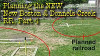 Return to "Planning the NEW New Boston and Donnels Creek, Part 4"
 Return to "Planning the NEW New Boston and Donnels Creek, Part 3"
 Return to "Planning the NEW New Boston and Donnels Creek, Part 2"
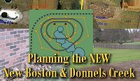 Return to "Planning the NEW New Boston and Donnels Creek, Part 1"
 Return to the New Boston and Donnels Creek RR Page
 Return to Family Garden Trains' Home Page