
Mallet Articulated Compound Locomotive (American Locomotive Company).—The Mallet articulated compound locomotive is one having two sets of cylinders, compounded together and driving independent groups of wheels. The two sets of cylinders are supplied with steam from a single boiler; which makes it practically two locomotives combined in one, and having only one boiler. The rear group of wheels is carried in frames rigidly attached to the boiler in the usual manner, while the frames which carry the front group of wheels are not secured to the boiler, but support it by means of sliding bearings. There is a hinged connection between the frames of the front engine and those of the rear engine, about which the former is permitted a limited swing in relation to the latter. It will be seen that the front group is a truck which swivels radially about its articulated connection with the rear group, when the locomotive passes through a curve. It is from this feature that the articulated type of locomotive derives its name.
Because of the fact that only the rear group of wheels is carried in rigid frames, the articulated type of locomotive provides a short rigid wheel base capable of passing through curves of short radius. At the same time, the total number of wheels is greater than in the ordinary types of locomotives; and the weight is distributed over a greater number of axles. Consequently, an enormous weight with corresponding tractive power may be provided in this type without an excessive weight per wheel on the rail. In an articulated compound locomotive having twice as many driving wheels as a given locomotive of the rigid-frame type, double the tractive power of the latter is available, with the same weight per driving wheel on the rail and with no increase in the length of the rigid wheel base. Or vice versa, with the same tractive power in each case, the weight per driving wheel on the rail of the articulated compound locomotive may, by the use of the proper wheel arrangement, be reduced to one-half of that of a given locomotive of any of the types in ordinary use.
The work being divided between two sets of pistons, crank pins, rods, and driving axles, an enormous tractive power is obtained in the articulated compound locomotive with practically no increase in the weights of the moving parts over those of a locomotive of the rigid-frame type, having half the tractive power; or with the same tractive power in each case the moving parts of the articulated locomotive may be made much lighter than those of locomotives of other types.
In addition to the advantages due to its wheel arrangement, the articulated compound locomotive possesses all those resulting from compounding the steam. This type of compound locomotive is what is known as a two-stage compound; that is, the steam is used successively in two sets of cylinders. Steam from the boiler is admitted to the first set or high pressure cylinders, which ordinarily drive the rear group of wheels; and, having done work in those cylinders, is then used over again in the second set or low pressure cylinders which are connected to the front group of wheels. From the low pressure cylinders, the steam is exhausted to the atmosphere.
Between the high and low pressure cylinders and connecting the two is a large pipe called the receiver, into which the steam from the high pressure cylinders exhausts when the locomotive is working compound. The receiver is simply a reservoir in which the exhaust steam from the high pressure cylinders is stored until it is required by the low pressure cylinders. From the receiver, the steam is admitted into the low pressure cylinders by their valves in the usual manner.
The low pressure cylinders have a larger piston area than the high pressure cylinders, the ratios between the two being such that, at the ordinary working cut-off, the steam at the lower pressure per square inch acting against the larger piston area, exerts the same force as the higher pressure steam acting on the smaller area. Consequently, the high and low pressure cylinders having the same stroke, each set of cylinders ordinarily does practically the same amount of work.
By using the steam successively in two sets of cylinders, a greater range of expansion is obtained than in a simple or single expansion locomotive. In other words, the difference between the pressure of the steam entering the high pressure cylinders and the pressure it has when the exhaust from the low pressure cylinders opens, is greater than in the case of the simple locomotive.
In a simple locomotive, the steam is ordinarily expanded only four times, while in a two-stage compound six or seven expansions are obtained. As a result, more work is performed by the same amount of steam in a compound than in a simple locomotive; and a considerable saving in coal and water consumption is thereby effected.
Moreover, compounding divides the range of temperature between the two sets of cylinders; so that the condensation in the cylinders is reduced, which effects a further saving in fuel and water consumption.
In every compound locomotive some provision must be made for admitting steam direct from the boiler to the low pressure cylinders in starting and until the exhaust from the high pressure cylinders supplies the low pressure cylinders with steam. Also, provision is usually made by which in case of emergency when additional hauling capacity is required, the locomotive may be changed from working compound into simple with an increase in power. In this articulated compound locomotive, these functions are performed by a special mechanism called the intercepting valve, which is located between the receiver and the exhaust passages from the high pressure cylinders.
Another device used by some locomotive builders, in place of the intercepting valve, is an arrangement by which, on opening a valve operated from the cab, communication is established between the two ends of the high pressure cylinder through a by-pass pipe; and live steam reduced in pressure by passing through this pipe is admitted to the receiver and so to the low pressure cylinders.
With the by-pass arrangement, when the locomotive is working simple, live steam is necessarily admitted to both sides of the high pressure pistons. Consequently, these pistons are very nearly balanced. At the same time, the live steam which is admitted to the low pressure cylinders is reduced in pressure. The result is that under these conditions, when the locomotive is starting or working simple, practically all of the work is done by the low pressure cylinders, and little, if any, increase in power is secured.
In the American Locomotive Company's system of compounding, the intercepting valve is so designed that when the engine is working simple the exhaust from the high pressure cylinder passes directly to the atmosphere and the valve cuts off communication between the receiver and the exhaust side of the high pressure pistons, thus relieving them of back pressure, except that of the steam exhausting to the atmosphere. Moreover, the live steam from the boiler reduced to a pressure of somewhat above the ordinary pressure in the receiver is admitted to the low pressure cylinder. Hence, the low pressure pistons are exerting more power than when working compound. This additional power, added to that secured in the high pressure cylinders, because of the reduction of the back pressure, gives a total increase in power when- working simple of about 20 per cent. The intercepting valve also automatically regulates the pressure of the live steam entering the receiver when starting and when working simple, keeping it at such a pressure that each of the four cylinders does practically the same amount of work.
Among the distinctive features of this articulated compound locomotive, practically, the only ones which enter into its operation are the intercepting valve, the power reversing gear, and the by-pass valves.
The intercepting valve is identical in principle with that used on the two-cylinder cross-compound locomotives known as the Richmond Compound, differing from the latter only in certain modifications of the design which the use of four cylinders instead of two necessitates. Engineers, therefore, who have operated the two-cylinder cross-compound of this build, will be perfectly familiar with the construction and operation of the intercepting valve as applied to this locomotive.
This valve is located in the saddle of the left high pressure cylinder, to the left of the vertical and above the horizontal center line of the cylinders. It consists, in reality, of three valves, viz., the intercepting valve, the reducing valve or sleeve, and the emergency or high pressure valve.
 The various parts comprising the
whole mechanism are shown in detail in Fig. 2.
The various parts comprising the
whole mechanism are shown in detail in Fig. 2.
Parts 2, 3 and 5 constitute the intercepting valve proper.
This valve shuts off, at the proper time, communication between the receiver and the high pressure cylinders, to prevent the pressure in the receiver backing up against the high pressure pistons, when the locomotive is working with live steam in all four cylinders.
The reducing valve or sleeve, 1, fits on the stem of the intercepting valve, 2, along which it is free to slide longitudinally. Its duty is three-fold:
First, to close the intercepting valve in starting and when the locomotive is changed from compound to simple working;
Second, to let live steam from the boiler into the receiver and low pressure steam chests in starting and when the locomotive is working simple;
Third, to regulate the supply of this live steam and keep its pressure at a predetermined amount.
The emergency or high pressure exhaust valve, 6, which is located at one of the outer ends of the intercepting valve chamber, is the device which makes it possible to change the locomotive from compound to simple working (that is, using live steam in all four cylinders).
A wrought iron pipe leads from the emergency valve chamber along the left side of the locomotive to an elbow at the rear of the main exhaust pipe. This elbow connects wits. a passage surrounding the main exhaust opening.
When the locomotive is changed into simple working, the emergency valve, 6, is opened, which allows the exhaust steam from the high pressure cylinders to pass through the wrought iron pipe to the exhaust pipe in the smoke box and to the atmosphere.
 Opening of the emergency valve
is accomplished by opening the emergency operating valve, which
is indicated by the letter N in Fig. 3. When the emergency operating
valve is closed (when the locomotive is working compound), the
handle of the valve points forward.
Opening of the emergency valve
is accomplished by opening the emergency operating valve, which
is indicated by the letter N in Fig. 3. When the emergency operating
valve is closed (when the locomotive is working compound), the
handle of the valve points forward.
To open the emergency operating valve, N, and change the locomotive into simple, the handle must be turned so as to point backward. The opening and closing of the emergency valve, 6, is thus under the control of the engineer.
It is important to bear in mind that the emergency valve, as its name indicates, should ordinarily be used only when the locomotive cannot otherwise move the train; and, as soon as a speed of three to four miles per hour has been attained, the locomotive should be changed back to compound.
Except for changing the locomotive into simple, the movements of all the parts of the intercepting valves are automatic.
The illustrations in Figs. 4, 5, 6 and 7 show the entire mechanism
assembled, and the arrangement of the various steam pipes and
passages These illustrations also give the intercepting valve
in its four different positions; namely:
Fig. 4, the moment after the throttle is open when starting
in the ordinary way, the reducing valve, 1, being open and the
intercepting valve, 2, and the emergency valve, 6, closed;
Fig. 5, at the time when the predetermined pressure has
been reached in the receiver pipe, when the reducing valve, 1,
is closed arid the other parts remain in the same position as
in Fig. 4;
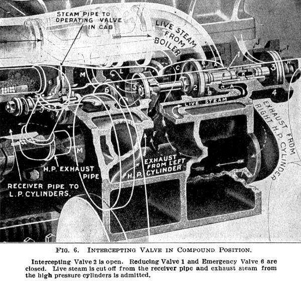
Fig. 6, in the compound position, when the intercepting
valve, 2, is open and the reducing valve, 1, and the emergency
valve, 6, are closed;
Fig. 7, in simple position, when the emergency or high
pressure exhaust valve, 6, and the reducing valve, 1, are open,
and the intercepting valve, 2, is closed.
In these illustrations, the course of the steam is indicated by arrows, and helps to make clear the explanation of the principle and operation of this system of compounding.
As will be seen from Fig. 7, the reducing valve, 1, is so fitted on the stem of the intercepting valve, 2, that when the former opens, it closes the latter, and vice versa. The reducing valve, however, can be closed without opening the intercepting valve.
Referring to Fig. 4, live steam from the boiler is, as indicated by the arrows, always admitted through the cored passages in the cylinder casting to the chamber, A, formed in the intercepting valve chamber head, 4, and surrounding the reducing valve, 1. Chamber C communicates with the receiver pipe or steam passage to the low pressure cylinders, and chamber F connects directly with the exhaust passages from the high pressure cylinders. The chamber L communicates with chamber M through the emergency or high pressure exhaust valve, 6. The latter chamber is connected with the exhaust pipe in the smoke box, as previously explained.

With the intercepting valve in the position shown in Fig. 4, steam from the boiler, following the course of the arrows, flows through the passage in the left high pressure cylinder to chamber A, and acting against the shoulder, E, of the reducing valve, 1, has forced this valve open or inward, closing the intercepting valve, 2, and uncovering the ports, B. This allows live steam to pass into the chamber C, and thence into the receiver and to the low pressure steam chests and cylinders. Live steam, at the same time, passes through the high pressure valve into the high pressure cylinders in the ordinary way. The intercepting valve, 2, being closed, communication between the exhaust passage, F, from the high pressure cylinders and the chamber, C, is cut off. This thus prevents the pressure in this latter chamber from backing up against the exhaust side of the high pressure pistons; and, consequently, these start free from back pressure; while, at the same time, the low pressure cylinders are being supplied with steam direct from the boiler. The pressure of this steam is so regulated by the reducing valve, 1, that it bears the same relation to the boiler pressure as the high pressure piston areas bear to the low pressure piston areas, thus making the work in all four cylinders equal (the high and low pressure cylinders having the same length of stroke). For instance, if the area of the low pressure cylinder is two and one-half times the area of the high pressure cylinder, then the reducing valve, 1, would be so designed as to reduce the pressure of the live steam admitted by it to chamber C, to 1 divided by 2.5 or 40 per cent. of the boiler pressure.
From the above, it will be seen that the locomotive automatically starts with live steam in all four cylinders, or, in other words, as a single expansion engine.
Piston, 3, and the chamber, H, in the outer end of the intercepting valve chamber head, 4, constitute simply an air dash-pot, to prevent slamming of the valves when changing from compound to simple when running.
Fig. 5 represents the intercepting valve at the moment when the predetermined maximum pressure in the low pressure steam chests is reached. In this case, it will be noticed that the positions of the valves are the same as in Fig. 4, except that the reducing valve, 1, has been moved out, closing the ports, B, thus cutting off the supply of live steam to the chamber C, and to the low pressure steam chests; until by the movement of the low pressure pistons the pressure in that chamber has been lowered to the required amount.

The reducing valve automatically keeps the pressure in the chamber C down to the desired amount because of the fact that the area of the shoulder E is, as previously stated, usually 1 divided by 2.5 or 40 per cent. of the area of the end D of the valve. Consequently, when the pressure in the chamber C exceeds 40 per cent. of the boiler pressure, it will overcome the force of the steam at boiler pressure, acting on the shoulder E; and move the reducing valve, 1, outward, closing ports B.
The intercepting valve automatically assumes the compound position, Fig. 6, after one or two revolutions of the driving wheels. In this position, the intercepting valve 2 is opened, allowing the exhaust steam from the high pressure cylinders to pass into the chamber C, and so to the receiver and the low pressure cylinders. The opening of the intercepting valve 2 has closed the reducing valve, 1, which thus cuts off the supply of live steam to the chamber C and receiver.
The principle by which these movements are automatically performed may need some explanation. The exhaust steam from the high pressure cylinders in the chamber F acting against the inner face of the intercepting valve, 2, and also against the inner end of the intercepting valve stem .(being admitted to the chamber L through the holes in the unbalancing valve, 5), tends to open the intercepting valve 2. This force is resisted by the pressure on the outer face of the intercepting valve 2, the pressure on the outer and inner faces of the unbalancing valve, 5, being balanced. The combined areas of the face of the intercepting valve 2 and the end of its stem are greater than the area of the outer face of the valve. Thus steam in the chamber F at a lower pressure acting against this larger area overcomes the resistance of the higher pressure steam in chamber C and forces the valve into the position shown. This principle is the same as in the case of the reducing valve previously explained.
These areas are usually so proportioned that when the pressure in the chamber F is 30 per cent. of the boiler pressure, it overcomes the resistance of the steam in the chamber C at a pressure of 40 per cent. of boiler pressure.
As will be seen from the above, when the locomotive is working compound the low pressure steam chests receive all of their steam from the exhaust from the high pressure cylinders through chambers F and C and the receiver, the ports B having been closed by the outward movement of the intercepting valve 2. At full stroke, the pressure on the low pressure pistons would be, approximately, 30 per cent. of the boiler pressure; while, on the high pressure pistons, would be exerted the pressure which the live steam from the boiler has, minus the 30 per cent. in the receiver which acts on their exhaust sides. The pull on the cross-heads of all four cylinders is practically equal, as the products of the several piston areas multiplied by their respective pressures are equal in each case.
Should the maximum power of the locomotive be required in starting or in ascending a heavy grade, it may be had at any time by simply turning the emergency operating valve N in the cab so that the handle points to the rear. The intercepting valve will then assume the position shown in Fig. 7.

Opening the emergency operating valve admits live steam into the chamber G, which forces the emergency valve, 6, open against the resistance of its own spring plus the pressure of the steam in the chamber L (which is receiver pressure).
On the opening of the emergency exhaust valve, 6, the steam in the chamber L is immediately released. This unbalances the intercepting valve, 2, with the result that the reducing valve, 1, is moved inward or opened by the pressure of the steam from the boiler in chamber A acting against the shoulder E. The reducing valve, 1, carries the intercepting valve 2 inward with it, closing the latter, the two valves assuming the position shown in Fig. 7. Communication between the chamber C and the chamber F, into which the steam from the high pressure cylinders exhausts, is thus cut off; while live steam from the boiler, at a pressure reduced to about 40 per cent. of the boiler pressure, is allowed to pass through the ports B into the chamber C and thence through the receiver to the low pressure steam chests.
By the use of the intermediate chamber L between the chamber F and the emergency valve, 6, which is exhausted the instant that valve is opened, the intercepting valve 2 is closed and the reducing valve 1 opened before, or at the same moment, that the receiver is actually exhausted.
Consequently, there is no drop of pressure in the low pressure steam chests during the change from compound to simple or prior to the entrance of live steam into the low pressure steam chests.
As the emergency exhaust valve, 6, is kept open by the pressure of the steam admitted to the outer side of the piston 8 by the opening of the emergency operating valve in the cab, the exhaust steam from the high pressure cylinders passes through the chamber F into the chambers L and M, and so into the high pressure exhaust pipe and to the atmosphere.
Thus when the intercepting valve is in position shown in Fig. 7, that is, when the locomotive is working simple, the high pressure pistons are relieved of the back pressure amounting to 30 per cent. of the boiler pressure, which acts against them when the locomotive is working compound, with the intercepting valve in Fig. 6. On the other hand, the low pressure cylinders are receiving steam direct from the boiler at a pressure of 40 per cent. of that which it has in the boiler, instead of exhaust steam from the high pressure cylinders at a pressure of only 30 per cent. of boiler pressure, as when the locomotive is working compound. This explains the 20 per cent. increase in the normal maximum power, which, as already stated, is obtained by changing the locomotive into simple. The increase would be greater were it not for the wire-drawing of the steam through the restricted area of the ports B, which are intentionally reduced for operation under this condition. As it is, the actual increase in power at speeds of from three to four miles per hour would not be greater than the amount given above.
The reducing valve, 1, is so designed that at speeds of more than three or four miles an hour no increase in power is obtained by changing the locomotive into simple. This is done in order that the emergency feature will not be misused, with injurious effect on the machinery and the sacrifice of economy in fuel consumption.
If the pressure in the chamber C and consequently in the receiver pipe and the low pressure steam chests rises to more than 40 per cent. of the boiler pressure when the engine is working simple, the reducing valve, 1, will be forced outward to the position it has in Fig. 5; that is, closing the ports B and shutting off the live steam from the chamber C. The other parts of the valve, however, will remain in the same position as shown in Fig. 7. The reducing valve 1 automatically closes under the conditions above stated.
Upon the movement of the low pressure pistons, the steam pressure in the chamber C will be reduced; and the boiler pressure acting upon the small shoulder E would again force the reducing valve 1 inward to its position in Fig. 7, opening the ports B. Thus the pressure in the chamber C and low pressure steam chests would be again raised to the required 40 per cent. of the boiler pressure. This alternate opening and closing of the reducing valve 1 will continue as long as the displacement of the low pressure pistons does not exceed the supply of steam that comes through the ports B. When this condition occurs, the reducing valve 1 will remain open.
These facts explain why, if the locomotive starts to slip when it is changed into simple, it automatically ceases without necessitating closing the throttle; since, with the rapid movement of the low pressure pistons, the power of those engines is reduced; and, with the increased exhaust from the high pressure engines passing through the comparatively restricted opening of the emergency valve 6, the back pressure on the high pressure pistons is increased, reducing the effective power in those cylinders.
It is very important for the engineer to remember that, the locomotive having been changed into simple working by opening the emergency operating valve N in the cab, it is necessary to close this valve (that is, turn it so that the handle points forward), in order to change the locomotive back to compound or normal working. With the emergency operating valve closed, the steam will be exhausted from the chamber G in front of the piston 8. The tension of the spring, assisted by the steam pressure upon the inner end of the emergency exhaust valve 6, will then return that valve to its seat, thus preventing the exliaust steam from the high pressure cylinders escaping to the stack. A few exhausts from the high pressure cylinders will, then, soon raise the pressure in the chamber F and force the intercepting valve 2, and with it the reducing valve 1, to assume the compound position, as shown in Fig. 6.
If, upon starting the locomotive, it is desired to prevent the valves from changing automatically to the compound position, the emergency valve 6 may be opened in advance by opening the emergency operating valve N, turning the handle to the rear. This, as previously explained, will prevent the pressure in the chamber F from rising sufficiently to force the intercepting valve 2 open.
In changing from compound to simple when running, the sudden unbalancing of the intercepting valve 2, tends to close this valve rapidly, with the result that it would slain, were it not for the dash-pot, which prevents this. The dash-pot piston 3 at the outer end of the intercepting valve stem works in the cylinder H formed in the outer end of the intercepting valve chamber head 4. When the intercepting valve is forced inward under full pressure, its too rapid motion is prevented by the slow escape of the air from under the piston 3 through the small port J. This is practically the only function of the dash-pot. The port K, extending through the center of the intercepting valve stein half way to the inner end, permits the escape of any steam that may leak past the small rings on the intercepting valve stem and reducing valve 1.
All of the ports of the intercepting valve have important duties to perform, and their location and sizes must not be changed.
From the above description of the intercepting valve, it will be seen that to start a train with an articulated compound it is usually only necessary to open the throttle in the ordinary way with the reverse lever in the position required for the weight of the train or, ordinarily, in the extreme notch; and with the cylinder cocks open. The intercepting valve will automatically assume the position shown in Fig. 4, and the locomotive will work simple until the pressure in the receiver has raised sufficiently to force the intercepting valve 2 into position shown in Fig. 6, or compound position.
If the locomotive fails to move the train when started in this way, or is about to stall on a steep grade, it should be changed into simple working by turning the handle of the emergency operating valve in the cab, so that it points to the rear, which causes the intercepting valve to assume position shown in Fig. 7.
There is no increased tendency for the locomotive to slip when working simple; and, moreover, when it does slip, the slipping is automatically arrested after only a few inches of movement of the piston. If, however, the locomotive starts to slip, it is advisable to use sand, should the rail conditions be at all unfavorable.
The engineer can easily tell whether the locomotive is working simple or compound either by the sound of the exhaust or by the position of the emergency operating valve in the cab. When working simple there are eight exhausts to each revolution of the wheels, and only four when working compound. In the former case the exhaust has more the sound of a continuous blow, the separate exhausts being less distinct. When working compound, the handle of the emergency operating valve, as stated, points forward, and to the rear when working simple.
If the low pressure engine fails to start when the throttle is open, the trouble may lie in the reducing valve 1 having stuck in the closed position, due to the fact that it had not been properly lubricated or some foreign matter had worked into the bore of the valve. In such an event the admission ports B, Fig. 4, would be closed and no steam could get to the low pressure cylinder.
Such a difficulty can ordinarily be remedied by giving the reducing valve a little more feed of oil for a few minutes; or, if necessary, the cover of the dash-pot H may be removed and with a piece of bent ¼-inch wire the reducing valve 1 may be moved in and out a few times, after which it will probably clear itself when the throttle is open.
The intercepting valve should be given a liberal feed of oil for a minute before starting and occasionally during long runs when the throttle is not shut off for a considerable length of time. Outside of this, one drop of oil every four or five minutes is ordinarily ample when running.
Because of the size and weight of the parts of the valve motion of this articulated compound locomotive, a power reversing gear is generally applied to operate the reverse lever. This is an engine consisting of two cylinders, one an air cylinder and the other filled with oil. The two cylinders are set one ahead of the other, and are usually bolted to the underside of the mudring or some other convenient location.
Fig. 8 shows the arrangement and construction of this mechanism. In this case the forward one is the air cylinder and the rear the oil cylinder, although this arrangement is usually reversed and can be made whichever the circumstances require. In any arrangement both pistons are mounted on a common piston rod which is connected to either the main reverse lever, or, as in the illustration, to an extension of the reverse shaft arm.
Between the two cylinders are the packing boxes for the common piston rod, and there is also a stuffing box at the air end of the cylinder for the rod connecting the piston with the reverse lever or shaft, as the case may be. Both pistons are packed with leather packing, that in the air cylinder being held out by spring rings. The valves of both cylinders are conical, that for the air cylinders having four openings in addition to the exhaust cavity, while the oil cylinder valve has two crossed passages.
The valves of the air and oil cylinders are operated by an auxiliary reverse lever R to which they are connected by a rod. This lever is pivoted on the main lever Q at the point W. It is provided with a latch with teeth that fit in a quadrant in the same manner as the main lever. This latch is so interlocked with the latch of the main reverse lever Q that raising the former raises the latter, which cannot drop again unless the main reverse lever Q is in its normal position relative to the auxiliary lever R.
The levers are so designed that when the two latches are lifted the auxiliary reverse lever R is allowed sufficient movement abut its pivot, point W (limited by lugs on the main reverse lever latch) to give a full opening of the valves of the air and oil cylinders.
When a change in cut-off is desired the latch of the auxiliary lever R is released, which also unlatches the main reverse lever Q. If the main reverse lever Q is to be thrown ahead, the auxiliary lever is moved forward about its pivot point W, and back, if it is desired to move the main lever in that direction. The movement of the auxiliary lever R, forward or back, swings its lower end Y which operates the valves of the, air and oil cylinders; and the valve motion is moved in the desired direction.
For instance, when the auxiliary lever is pushed forward, its lower end Y is drawn back. This turns the valve of the air cylinder so that the air is admitted through the air inlet 13 to the front of the piston, and the exhaust port 14 establishes communication between the rear end of the air cylinder and the exhaust to the atmosphere. At the same time the crossed passages of the oil cylinder valve are so turned as to allow the oil in the cylinder to flow from one end to the other. The air and oil pistons thus move back and the valve gear is moved forward. The slow flow of the oil in the oil cylinder prevents the too rapid movement of the reverse lever Q.
The auxiliary lever R, being pivoted on the main reverse lever Q, moves with the latter, and when the gear is to be changed must be kept in motion until the desired notch in the quadrant is reached and then latched. By stopping the movement of the auxiliary lever, the gear automatically moves the main reverse lever up to its normal position relative to the former, when it also latches, as already stated. This also automatically closes the valves of both the air and oil cylinders, giving both an oil and a positive lock to the gear.

Except in case of lack of air pressure or any accident to the power reversing gear, the valve motion is handled entirely by the auxiliary reverse lever R. For this reason the practice is to cut off that portion of the main reverse lever Q which ordinarily projects above the deck of the cab, thus leaving more room for the engineer. . A separate handle is provided for the main reverse lever, which may be easily applied in case of accident to the power reversing gear.
It is, of course, important that the air and oil valves be properly set so that the valve openings and cylinder ports match up properly in the different positions. For example, a quarter of a turn of the oil valve one way or the other would result in the valve being blanked instead of open when the auxiliary lever R was moved about its pivot point. The gear could not, then, be operated, as the oil could not circulate from one end of the oil cylinder to the other. If, therefore, the power reversing gear fails to operate when the valves are supposedly opened and nothing has happened to the air supply, first examine the valves to see that they are in their proper position.
The function of the oil cylinder is to prevent the too rapid movement of the reversing gear when a change of cut-off is made. It is imperative, therefore, that this cylinder be always kept full of oil. The frequency with which it should be filled depends on the condition of its piston and piston rod packing and these should, therefore, be kept in good condition. If the reversing gear operates too rapidly, this indicates that there is a lack of oil in the oil cylinder and this should be refilled and the leakages stopped.
In case of any repairs to the power reversing gear, especial attention should be given to see that it is properly adjusted when set up so that when the gear is operated the main reverse lever will automatically be moved to its normal position relative to the auxiliary lever and properly latch. If the gear is not properly adjusted, the latch of the main reverse lever will not engage properly with the teeth of the quadrant. In consequence the latch of the auxiliary lever will have to hold the gear with the result that it will be quickly worn.
Another feature which plays a most important part in the successful operation of the articulated compound locomotive, and so should be clearly understood by the engineer, is the by-pass valves.
The purpose of these valves is to prevent the injurious effects which would otherwise result from the pumping action of the large low pressure pistons when the locomotive is drifting.

These valves are so designed that they automatically establish communication between the two ends of the cylinder, when the engine is running with the throttle closed, thus performing several important functions:
First, they prevent alternating vacuum and compression in the cylinders when the locomotive is drifting, thus insuring the free movement of the pistons.
Second, by permitting the circulation of the free air drawn into the cylinders through the vacuum-relief valves, they prevent this air from being overheated by the churning of the pistons and thus destroying the lubrication, when the locomotive is drifting down a long hill.
Third, by destroying the vacuum which, without them, would be formed by the large piston, they prevent the smoke and gases from the smoke box being sucked into the cylinder.
Fourth, they prevent excessive fanning of the fire from the pumping action of the large pistons when drifting
These valves are located in chambers cast in the outside of each low pressure cylinder. Their construction is shown in Fig. 9. There are two valves to each cylinder. The lower view in the illustration shows the two valves U with the heads T of the chambers in which they are located; while the upper view shows the valves alone without the valve chamber heads.
Fig. 10 illustrates the arrangement of the valves when assembled in their chamber and their relation to the steam ports in the cylinders.
In position A of this latter figure, the valves U are in the position they assume when the throttle is open. In this position the steam passing from the steam chest ports through the small ports S in the head T of the valve chamber, as indicated by the arrows, acts against the outer ends of the valves U and keeps them against their seats, cutting off communication between the admission ports of the cylinders.
Position B of Fig. 10 is the one the by-pass valves U automatically takes when the throttle is closed. In that event the atmospheric pressure admitted through the small air vent in the valve chamber forces the valves U open, closing the steam chest ports and establishing communication between the admission ports at either end of the cylinders. This permits circulation from one end of the cylinder to the other when the locomotive is drifting, accomplishing the necessary results enumerated.
 It is strongly recommended, therefore,
that in drifting the reverse lever be kept at ¾-stroke
or more, since when operated in this way the locomotive will drift
freely.
It is strongly recommended, therefore,
that in drifting the reverse lever be kept at ¾-stroke
or more, since when operated in this way the locomotive will drift
freely.
As the by-pass valves perform such important duties, it is essential that they be properly cared for and kept in good condition, to prevent them from sticking. The engineer can tell at once if the by-pass valves are stuck open, as, in that case, steam will blow from the small pipe projecting from under the jacket midway between the ends of the cylinder. This pipe connects to the air vent in the center of the chamber containing the valves.
From the above description it will be seen that if the bypass valves stick open it will cause a severe blow. When the locomotive is first put into service the by-pass valves should be taken out and cleaned quite frequently to keep them free of core sand which will undoubtedly work in. After this has been done a few times they require only ordinary attention.
If the low pressure engines are heard to thump as if a piston, crosshead or box were loose and the locomotive does not drift freely, the trouble probably lies in the bypass valves being stuck closed by being gummed, and these should be taken out and cleaned at the first opportunity.
Sticking of the by-pass valves may be caused by smoke box gases being sucked into the cylinders by the pistons when the locomotive is drifting with the reverse lever "hooked up." These gases would be sent circulating through the bypass valves which are oily from the steam, and the soot may stick to them and form a gum. This gum hardens gradually and the valves ultimately work so hard that the comparatively light suction in the steam chest is not strong enough to open them. On this account periodical cleaning of these valves should be made.
The possibility of smoke and gases being sucked into the cylinders will be minimized, if the reverse lever is kept at ¾-stroke or more when the locomotive is drifting.
In the high pressure steam chests or some other convenient place which is in communication with the steam chests, are located vacuum valves. The function of these valves is to admit free air into the steam chests when the locomotive is drifting so as to avoid a vacuum and give a moderate flow of air through the cylinders.
The low pressure cylinders are equipped with combined vacuum and relief valves which in addition to having functions similar to the vacuum valves of the high pressure cylinders also regulate the steam pressure in the low pressure steam chests. These relief valves are set at 45 per cent of the boiler pressure.
As these valves relieve any excessive pressure in the low pressure cylinders, they should be tested occasionally to see that they are correctly set.
From the previous description of the intercepting valve it will be seen that when the locomotive is working compound the packing rings of the high pressure valves and pistons alone separate the boiler pressure from the pressure in the receiver and low pressure cylinders. Consequently if there was a blow in these packing rings, the pressure in the receiver would be increased, causing the relief valves in the low pressure steam chests to blow off. Therefore, if these valves rise from their seats frequently when the locomotive is working compound, it might be due to the fact that there was a blow in either the valves or the pistons of the high pressure cylinders, and these should be tested.
To test for blows simply throw the emergency operating valve in the cab to the simple position, namely, with the handle pointing to the rear. Spot the locomotive and test the same as a simple locomotive.
Another feature peculiar to the articulated compound locomotive is the flexible ball and slip joint steam pipe connections.
In this articulated compound locomotive there is a ball joint connection between the receiver pipe and the high pressure cylinders, a slip joint connection between the receiver pipe and the Y-pipe by which the steam is carried to the steam passages of the low pressure cylinders, a ball joint connection between the exhaust pipe flexible connection and the low pressure cylinders and also between the former and the exhaust pipe in the smoke box. This exhaust pipe flexible connection is likewise provided with a slip joint to allow for the variations in its length when the engine rounds a curve. The construction of these flexible connections is shown in Fig. 11.
As will be noticed, the ball joints consist of a ball-bearing, gland, stuffing box and packing, while in the slip joints the construction is very much the same, without the ball-bearing.
The packing in both classes of joints consists of a fiber material. The free nominal size of the packing rings is five-eighth inch square in section and they are hammered and worked down to one-half inch square before being applied, which makes them soft and pliable.
In the case of the receiver pipe joint at the high pressure cylinders, a brass ring of elongated diamond section is inserted in the center of the packing. As this ring is just the width of the packing space it seals all the joints in the packing rings proper and forces them tightly against the inside of the box and against the ball.
In repacking the joint this brass ring should be removed, all the packing rings inspected, new rings put in where necessary and the ring put back in its proper place. In every case the original arrangement of joint packing should be preserved.
The diagram in Fig. 11 shows the method of arranging the rings. These must be cut to the correct lengths and the two ends in every case meet perfectly when in place. They are so arranged that the seams in any two adjacent rings are at least a quarter of a circle or 90 degrees apart, and all the seams in the entire set are at least one-eighth of a circle or 45 degrees from each other. The reference numbers on the diagram correspond to those on the packing drawings.


It is important, therefore, when the packing is renewed that care should be taken to arrange there in the manner shown, since if so arranged trouble from leaky joints will be avoided.
It is also essential that in renewing packing the same kind of packing should be used as that originally applied.
Owing to the fact that in the articulated compound locomotive a, long receiver pipe is generally employed and the ball joint is located in the vertical center of the pivot connection between the front and rear engines, there is very little movement in the ball joint and there is practically no tendency for this joint to leak.
In case there is any leakage it is usually due to the fact that the gland is not screwed in tight enough, and can be easily stopped by a turn or two on the gland bolts.
In locomotives of the articulated compound type vertical hanger or "trim" bolts X, Fig. 12, connect the upper rails of the rear frames with the lower rails of the front frames. These bolts have ball and socket bearings in the frame rails and sufficient play is allowed in the bolt holes to provide for the lateral movement of the front frames when the locomotive is passing through a curve. They serve to adjust the weights on the front and rear engines so that each bears its proportionate amount of the total load, and to keep the front frames in proper alignment. Ordinarily, therefore, the alignment of the engine may be easily adjusted if necessary by means of them without any other change in the spring rigging.
In designs of articulated compound locomotives having no front truck, where two sliding boiler bearings are employed, the front sliding bearing does not normally carry any load, but is merely an emergency stop in case of derailment or any unusual change in the alignment between the two frames. This bearing is so designed that when the front and rear frames are in proper alignment there is a clearance (ordinarily ¼ inch) between the upper and lower bearing and an equal amount between the upper bearing and the safety straps or clips, as indicated at Z and Z', Fig. 12.

An exception to the above rule should be noted in the case of class 0880 engines designed for over 16-degree curvature. In such designs the front bearing may sometimes be used for supporting a small part of the weight on the front engine, though a considerably less amount than when a front truck is used.
About ¾-inch total play is also always allowed between the rear draw casting (or jaw) and the front draw casting (or hinge) of the articulated connection. The hinge casting should not touch either the top or bottom of the jaw.
In the case of this articulated compound locomotive of one of the designs covered in the above rule, if the hinge casting of the articulated joint bears on the top of the jaw and the safety strap, or clips, of the front sliding boiler support bears close against the upper casting of this support, adjustment may be made by the "trim" bolts, which should be tightened up until the vertical play is approximately divided in each case.
On the other hand, if the bearing surfaces of the upper and lower castings of the front sliding support touch and the articulated hinge bears on the bottom of its jaw, adjustment should be made by loosening the "trim" bolts.
Should the upper and lower bearings of the front boiler support touch, while at the same time the articulated hinge bears on its top surface against the jaw, a liner plate of a thickness of about one-half the total play should be inserted between the sliding block of the rear boiler support and its saddle. This should give a satisfactory adjustment. To insert this liner, the rear bearing can be raised the required amount by tightening up the vertical suspension or "trim" bolts X, while the plate is fitted in, after which the nuts on the bolts should be eased off till the correct tension is secured and the proper adjustment is sure to be obtained.
If, on the other hand, the safety straps, or clips, bear on the upper casting of the front sliding boiler support and the articulated hinge bears on its bottom surface against its jaw, the sliding block of the rear sliding boiler support should be planed off an amount equal to one-half the total play.
When front trucks are used or where both bearings of the front engine support weight, the "trim" bolts are provided with a spring under the nut at one end in order to relieve the excessive load, which is liable to be concentrated on the rear bearing because of inequalities in the level of the track, or similar conditions.
In case of any breakdown in which one or more of the cylinders can be disconnected and the locomotive run in with the remaining cylinders active, simply throw the emergency operating valve N in the cab into the simple position and proceed as with a simple locomotive, namely, disconnect and block the disabled cylinder or cylinders. This is the only rule to follow and the only one to be remembered, and covers all cases of accidents which do not entirely disable the locomotive.
Always open the cylinder cocks in starting.
Usually the locomotive will start the train when the throttle is opened in the ordinary way with the reverse lever in the position required for the weight of the train or ordinarily in the extreme notch. If the locomotive fails to start the train when operated in this way, change it into simple working by turning the handle of the emergency operating valve in the cab so that it points to the rear. This same course should be followed if the engine is about to stall on a heavy grade. If the speed is over three or four miles an hour, no increase in power will be obtained by changing the locomotive into simple working.
When drifting, the reverse lever should be kept at ¾-stroke or more. As before stated, if this is done, the locomotive will drift freely.
The oil cylinder of the power reversing gear should always be kept full of oil. The piston and piston rod packing of the oil cylinder should be kept in good condition so as to prevent leakage. If the reversing gear operates too rapidly it indicates that there is not sufficient oil in the oil cylinder and this should be refilled and the leakages stopped.
If the reversing gear is not adjusted properly so that the latch of the main reverse lever does not engage with the teeth of the quadrant, the trouble should be remedied as soon as possible. If not properly adjusted, the locking of the reverse gear will be put almost entirely on the latch of the auxiliary lever, which is not designed for such duty and would, therefore, quickly wear.
The by-pass valves should be taken out and cleaned periodically to prevent them from being gummed and sticking. When the locomotive is first put into service, these valves should be cleaned quite frequently for a few times so as to keep them free from the core sand which is sure to work into them. Afterwards they will require only ordinary attention to work properly. When these valves are properly performing their functions, the locomotive will drift freely. If they stick open it will cause a severe blow, while if stuck in the closed position, it will cause a pounding in the low pressure engines.
The relief valves in the low pressure steam chests should be tested occasionally to see that they are correctly set at 45 per cent of the boiler pressure, as these valves relieve any excessive pressure in the steam chests.
REPAIRS TO FLEXIBLE JOINTS.—In renewing the packing of the flexible joints the same kind of packing should be used as that originally applied. Also care should be taken to keep the arrangement of the packing the same as that shown in the diagram in Fig. 11.
The brass ring of the receiver pipe joint at the high pressure cylinder may be removed in order to insert new packing, but the original arrangement of the joint packing should always be preserved.
LUBRICATION.—Give the intercepting valve a liberal feed of oil for a minute before starting and occasionally during long runs, when the throttle is not shut off for a considerable length of time. Except for this, one drop of oil to the intercepting valve every four or five minutes is ample when running.
Besides the intercepting valve, the other parts of the articulated compound locomotive which should be oiled, which are not found on the ordinary locomotive are:
Sliding boiler bearings on the front engine.
The ball joint in front of the high pressure cylinder (before starting on a trip).
The upper or rear ball joint of the exhaust pipe (before starting on a trip).
The lower or front ball joint of the exhaust pipe (before starting on a trip).
The bolt connecting the two engines.
The ball bearings of the vertical suspension or "trim" bolts which connect the upper rails of the rear frames with the lower rails of the front frames X, Fig. 12.
The ball bearings of the floating columns (if applied).
The piston rod packing of the cylinders of the power reversing gear.
The air cylinder of the power reversing gear, by means of the plug in the top of the cylinder (about once a week).
BLOWS.—To test for blows in the valves or pistons, throw the emergency operating valve in the cab to the simple position, namely, with the handle pointing to the rear. Spot the locomotive and test the same as a simple locomotive.
NOTE.—The Author is Indebted to The American Locomotive Company for the Foregoing Full and Authoritative Description.
Mallet Articulated Compound Locomotive (Baldwin Locomotive Company).—As the distinctive features of the Mallet locomotive have been described, the articulated boiler connection which does not form a part of that locomotive is given here, also the arrangement of the super-heater and reheater.

The flexible boiler connections used on the two following engines are entirely different in construction, engine 1158 having a double ball-jointed connection, while engine 1159 has a pleated or bellows form of connection.
On engine 1158 the connection consists of two cast iron sleeves, Fig. 2, fitted one within the other and provided with snap rings to keep the joint tight. Each sleeve forms a ball joint with a cast iron ring, which is bolted to the shell of the corresponding boiler section. These rings are made in halves, to facilitate assembling. The ball joints are kept tight by rings of soft metallic packing, which can be adjusted by set screws. The two boiler sections can thus move in any direction relative to one another and full provision is made for expansion and contraction.

On engine 1159 the joint is composed of sixty rings of high carbon steel having a thickness of No. 14 wire gauge, Fig. 3. These rings are ten inches wide and have an outside diameter of seventy-five and one-half-inches. They are made with. a set, so that, when placed adjacent to each other, they form a series of V-shaped joints. The adjacent rings are riveted together at the inside and bolted at the outside, and the connection is bolted in place between the front and rear boiler sections. The products of combustion traverse the flexible connection through a cylindrical flue forty-four inches in diameter. This flue is riveted to the rear boiler section and prevents cinders from lodging in the crevices between the connecting rings.

To assist in holding the boiler sections in alignment, a centering device is placed on each side on the horizontal center line of the boiler. This arrangement consists of a pair of helical springs, which are seated in cast steel brackets riveted to the shells of the front and rear boiler sections, Fig. 4. The springs are held in place between washers, carried by a horizontal thrust bar. When the engine enters a curve, the two boiler sections assume an angular position with reference to each other and by reason of the compression of the springs on the outer side the corresponding thrust bar is thrown into tension, thereby tending to bring the boiler sections back into alignment.

It is, of course, necessary in these locomotives to place flexible joints in all pipes which pass the articulated connections in the frames and boiler. This, however, introduces no objectionable complication. The steam piping is simplified, as no flexible joints are required in the exhaust connection between the low pressure cylinders and the smoke box. There is claimed to be a distinct advantage in the avoidance of sliding supports under the forward boiler section and the stability of the locomotive, when on curves, is not impaired by the lateral displacement of the boiler on the front frames, which necessarily occurs in the Mallet locomotive as usually built.
The arrangement of the superheater and reheater is practically the same on both engines. An open chamber is located in each boiler section adjacent to the flexible connection and these chambers contain the heaters, Fig. 5. The superheater is located in the rear boiler section and the reheater in the front section. These heaters are of the Jacobs type and each consists of a steel drum traversed by horizontal fire tubes.

The superheater is exposed to a higher temperature and steam pressure than the reheater and its tubes are welded at each end, while in the reheater the tubes are rolled and beaded. The heaters are fitted with internal baffle plates, so that the steam is compelled to follow a circuitous course among the tubes.

The throttle valve is connected with the superheater by an internal dry pipe and the steam enters the superheater at the top. There are two outlets, placed right and left in a steel casting on which the superheater drum is seated, and these outlets communicate directly with suitable passages which are cored in the high pressure cylinder saddle. The connections between the saddle and steam chests are effected by short elbow pipes.

| 
|
 |
 |
 |
 |
 |
Note: Family Garden Trains?, Garden Train Store?, Big Christmas Trains?, BIG Indoor Trains?, and BIG Train Store? are trademarks of Breakthrough Communications (www.btcomm.com). All information, data, text, and illustrations on this web site are Copyright (c) 1999, 2000, 2001, 2002, 2003, 2004, 2005, 2006, 2007, 2008, 2009, 2010, 2011, 2012, 2013 by Paul D. Race. Reuse or republication without prior written permission is specifically
forbidden.
Family Garden Trains is a participant in the Amazon Services LLC Associates Program, an affiliate advertising program designed to provide a means for sites to earn advertising fees by advertising and linking to amazon.com.
For more information, please contact us

 |  |
